Exidy Collex’n Kit Review
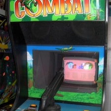
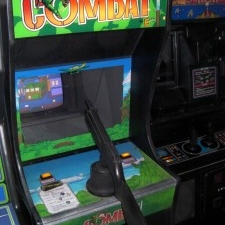
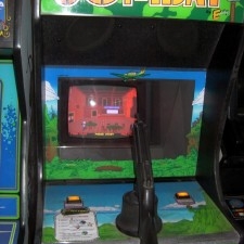
If you've not, I invite you to read my blog post about the Exidy Combat cabinet that I bought a few years back knowing one day I would add the kick ass multi-kit from Mike Doyle & Friend, the Exidy Collex'n. Basically it's an add on kit with 2 PCB's that takes pretty much any Exidy 440 PCB and offers up 9 different Exidy 440 games (well, 8.5 sort of, but more on that later).
I was ECSTATIC to read, in Decem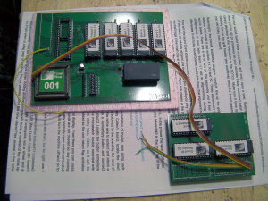 ber of 2013, that Mike Doyle was taking pre-payment on one FINAL RUN of his Exidy multigame kit. This final run is, I believe, the 3rd run in total, and it is my understanding that due to the inability to acquire a specific part that evidently is no longer being produced was the reason given. I was so exstatic that I clicked and paid immediately. It wasn't until a few minutes later that I realized that Mr. Doyle's post was literally 1 minute old at the time I was reading it. Evidently I was very lucky to see that post just seconds after he posted it as I was first to purchase as my serial plate indicates.
Over the next year and a half the final run would suffer a number of setbacks, including but not limited to the fact that the main board had to be re-designed. Evidently there were some issues with the last design that required an update (more can be read about it at Mikes blog). There was also an auto accident in there somewhere, not to mention the issues encountered with programming one (or more) of the chip(s). Over time the grumbling grew louder and louder from the community as there were some long stretches with little to no communication. I always kept the faith… though I would be remiss not to encourage Mr. Doyle to improve his communication when taking on projects such as this. The vast majority would be satisfied with monthly updates … even if it to report BAD or even NO news. People just want to be kept in the loop. In any case, my patience was rewarded the other day as I found Kit #001 in my mail box.
Upon opening the box, the kit was sparse. It included the two PCB's and… that's it. It was well packaged though. I found the install instructions on Mikes site … though it's the install instructions from the original kit. Mike did say the install instructions are the same though and he has mentioned the fact that he intends to update the instructions at some point. I printed the old kits instructions and got to work.
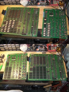
Pulling PCBs from the cabinet was a matter of removing a number of connectors and removing a single wood screw holding the PCB set in place. Once the screw is removed the two board set can be slid toward the back of the cabinet and then lifted out. Once on the bench the first order of business was to remove the top (smaller) sound PCB as we need to remove all sound and program EPROMs from both PCB's. There are 39 of them. They all came out without issue. For PCBs where it's easy to access the EPROMs I tend to prefer to use a small screwdriver to remove them rather than a chip puller. I've found with the cheap chip pullers I tend to tweak legs more often than if I take my time with a screwdriver.
After pulling the EPROM's I pulled the CPU (making it a total of 40 IC's that have to be removed) and installed it on the larger of the two PCBs of the kit. Pay attention to the notch in the CPU so as to ensure you orient the chip properly when installing it on the kits PCB. You can now install the larger PCB in the kit in to the now vacated CPU socket. This is the easiest part of installation as you only have one 40 pin socket to worry about. It should install quite easily. As that socket is the only thing holding the larger PCB be sure when you install it that all pins on both sides are lined up correctly and that when installed both sides of the socket have their pins fully installed… It would be difficult to install this PCB the wrong way as the satellite board would be hanging over the edge of the Exidy mainboard.
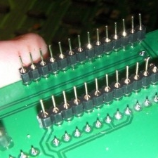
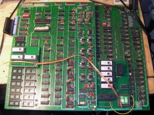 The next step is probably the most difficult as it's necessary to install the sound satellite PCB from the kit on the sound board of the Exidy PCB set and it requires that the pins for 3 sockets be lined up and installed. It takes quite a bit of pressure to install them… more than I expected… and the satellite PCB tends to pop up on one side while pressing down on the other. After a few minutes of careful pushing I had the sound satellite board attached… for now (more about this in a minute). The next step is to solder the three wires coming off the sound PCB to the chip located directly to the right and immediately below the sound satellite PCB (see the manual for exact location). This is where things went a little awry. The manual states that there are numbers "in white ink" on the sound satellite PCB indicating which wires were 1, 2, and 3. Unfortunately, this newer kit does NOT have the numbers silk-screened as the first two runs did. I looked everywhere (and have since seen a photo of the old kit showing the numbers)… they are NOT there. Unfortunately for me, after I'd spend some time looking for these numbers (even bringing out the magnifying glass) it was obvious there were no numbers. I figured I'd pull the sound PCB to look under it figuring there was a tiny possibility that the numbers got silked to the solder side. Bad move. First off… nope
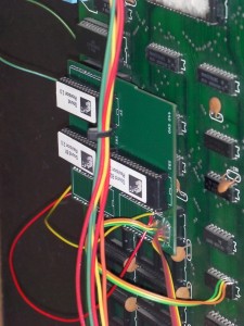 , those numbers aren't on the bottom side… so I was back to square 1. Secondly, evidently after installing correctly the first time some pins got slightly tweaked so when I went to install the 2nd time I ended up with not 1, not 2, not even 3…. but 4 bent pins. Three of those pins were right next to each other at the end of one row of pins… one odd duck was pin 5 from a completely different row of pins. After carefully attempting to bend back the pins I ended up immediately breaking off two… saving one… and one was on the verge of breaking… bad enough that it was "loose" feeling… so it came off two. Great. Now I have a $350.00 kit with 3 broken pins on the sound PCB. After discussing things with Mr. Doyle, he agreed to mail me some pins for replacement but by this point I was pretty dejected. After drinking a beer or three, I decided that I wanted to play me some Crossbow so out came the iron and solder. Ten minutes later I had jumpered all three pins to their proper locations on the Exidy sound board. It's not pretty, but it WORKED! That brought me back to the original issue I had which was the catalyst to all that went wrong with this installation… however by this time I was already informed what wires are 1, 2 and 3. Mike Doyle informed me that he plans on updating the instructions to include this info but in case someone is pulling their hair out trying to figure out which wire is which, if you look at the satellite PCB image to the right, The three wires are soldered to the PCB vertically in that photo… the wire closest to the chip is 1, the middle wire is 2, and the wire closest to the bottom edge of the satellite PCB is 3. If you expand the image you will see those wires are soldered to legs 1-2-3 of the chip to the right and slightly below the satellite PCB… in the order of wire 1 goes to leg1, wire 2 to leg 2 and wire 3 to leg 3. Once that is complete the last step is to decide how you are going to handle the pause button. The pause button is pretty important as you have to pause to then go back to the menu to select a different game. Alternatively you CAN simple power cycle the cabinet, but who wants to do that? There is a short yellow wire soldered to a chip on the main (larger) satellite PCB. That wire is to be run to a switch as is a ground of your choice (since I am on freeplay I just used one of the existing ground wires used for the coin switch). When this is complete it's time to fire the machine up to take a test run.
 With bated breath I plugged the cabinet, turned it on and … nothing. DAMN, oh wait… I'd forgotten the back door switch. OK, I pull the switch out and I hear sounds… sort of a low volume high pitch sound… then "AAAAARRRRRRRRRRRRRRRRRGGGGHHHHHHH" … knowing exactly what that sound meant I walked around to the front of the cabinet to see… the Exidy Collex'n titlescreen!! It's working! The scream used is the power on scream from Chiller… evidently there was some speculation this intro sample would be changed to something less startling… but alas it wasn't. Evidently it's pretty easy to change it… i may. It wouldn't bother me at all if it just made the sound once at power up, but unfortunately every time you go back to the menu you have to suffer through the scream. Oh well… it's a minor annoyance (that can be rectified and will one day). The good news though is that the kit was working!
I spent a good hour and a half or so playing each game. One game I was surprised by was Catch 22… Catch 22 is, evidently, the prototype of Combat. It's odd that it would be selected to be included but it is… the game appears to be pretty close to Combat however I did notice that it seems a little easier. I also noticed that the planes drop their bombs automatically. Aside fr om that I've not seen any real changes between the two games. Crossbow and Cheyenne both played as I remembered them. Having really only had exposure to those two Exidy 440 games back in the day, I was pleasantly surprised by a couple of the other games. Crackshot turned out to be a very fun game. I also really dig the Clay Pigeon game. Who Dunnit also looks quite interesting but seems to be very difficult… but difficulty is what I am used to having been stuck with Combat as the only 440 game to play for the last couple years. I also realized how much I suck at these games right now when I couldn't even get on the Crossbow high score board… which has a low score of 50,000 and a high score of 500,000… it's going to be a LONG TIME (if ever) before I can surmount that "stock" score.
Overall I am very pleased with the kit. The instructions DO need to be updated. It would also be nice if Mike changed the start up sound from the scream sound, but that is a minor gripe. I'm hoping the updated documentation describes how to get in to each games settings a little better… as currently I have no idea how to do it. I'd also like to figure out if it's possible to have the human colored skins (instead of green) in Chiller while maintaining freeplay mode (thus far this seems to be not possible but Torin, a friend (and KLOVian) who has had the older kit in the past says he THINKS his cabinet had the human colored skins while in freeplay on his older cabinet. Maybe there is something in the settings that I can't figure out how to get to? In due time.
EDIT: DIP Switch #2 on the audio PCB (8 bank switch) is what controls the Chiller skin tone. If its off you have flesh color skin but loose free play on Hit n Miss and Whodunit. If you have it on, all games are free play but you have green colored skin and blood (Zombies) on Chiller. It's only one dip you have to change and you can access it through the coin door. (Thanks to KLOVian "Chiller" for this information)
Here is a quick video I made showing how the kit works…
More Photos:



game settings have been documented since first run….. heres how you get to setting for each gameThat’s a little tricky. Normally you hold the start button down when you turn the machine on. The way you can do that with the menu is this. Hold the trigger down to select your game then hold the start button down. Quickly release and pull the trigger again. This will get you into the diagnostic memory and the gun calibration screen.Do I have to calibrate the gun for every game?No, not if you don’t want. There’s a utility in the diagnostic menu to… Read more »